'A Sensitive Field Strength Meter for Foxhunting', by Woody White - KZ4AK

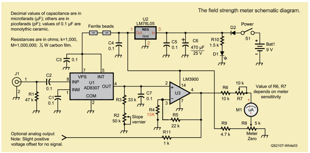
01. The Pins and 'IN' and 'OUT' Labels of U2, the LM78L05 Voltage Regulator, are incorrect.
02. One Lead of R5, the Feedback Resistor of the Non-Inverting Amplifier U3, is incorrectly connected to Ground. R5 should be connected between Pins 3 and 4 of U3 to produce the 1 + R5/R3 Voltage Gain from U1, to drive the Meter beyond full Scale (before calibration).
03. The Polarity of the Analog Meter is missing. The Positive Terminal of the Meter should be connected to R7.
Created: 19.06.2021, Modified: 19.06.2021
©2008 - 2099, Alle Rechte vorbehalten, SJWL
©2008 - 2099, Alle Rechte vorbehalten, SJWL