As experimentating radio amateurs, it sometimes happens that we make a short circuit, and somewhere a fuse blows. Do we have a new fuse at hand? Often not. Most transceivers have a 13.8 V output jack, useful for our many external devices. On my transceiver this outlet is fused by an internal 500 mA fuse. after having dismantled my transceiver for the nth time to replace this fuse, i decided that a quick circuit breaker could be a solution.
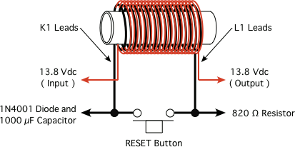
After some experimenting I came up with this solution, using only junk box parts. The heart of the construction is a fast reed relay. I then got the idea of supplying this relay with an extra coil, which senses the current to be protected.
The most important electrical factor for a relay is the number of ampere-turns. This is the current through the relay coil multiplied by the number of turns in that coil. I found a very small reed relay manufactured by Hamlin that operates on 5 V, with a coil resistance of 500 Ω and normally open (N.O.) contacts, rated to handle 0.5 A at 200 V. The closing and opening time for this relay is less than 1 ms. It should not be difficult to find reed relays with similar specifications from other manufacturers.
How many ampere-turns is necessary for this relay to close? I wound 50 turns around the original relay coil, and at 660 mA the relay closed. In other words, the relay needs 33 ampere-turns to close. I decided that the relay should close at 400 mA to protect the 500 mA fuse. hence, a coil with 82 turns of 0.5 mm (AWG no. 24) copper wire was wound on the reed relay, and as predicted, it closed at 400 mA. The resistance in the coil is negligible.
It is important that the magnetic fields made by the two coils are in phase, so that the resulting field is not weakened. That can best be controlled by means of a compass needle. Hold a compass close to the coil and watch which way the needle deflects when you turn on the supply voltage. Then connect the new coil so the compass needle deflects in the same direction.
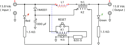
Relay K2 is a small 12 V relay with a coil resistance of 800 Ω, and its contacts are rated to handle 2 A.
From the schematic diagram of Figure 1, you can see that when voltage is applied, the green LED will light, and both relays K1 and K2 are turned OFF.
When the current through the extra relay coil, L1, exceed 400 mA, then relay K1 will turn ON and its N.O. contact will close and latch. Relay K2 will then turn ON, and its normally closed (N.C.) contacts open; and, the output current will be turned OFF, the red LED will turn ON, and the green LED will turn OFF.
Once the short circuit has been removed, press the RESET button and the circuit breaker is ready to operate again.
It is not necessary to put a diode across any of the relay coils. The capacitor value of 1000 µF is not critical. It ensures that the relays always get (almost) the full voltage.
By testing this device I found to my surprise that even a 100 mA fuse could withstand a direct short circuit through this device.
This idea of an extra current sensing relay coil may also be useful in other applications where one wishes to limit the current.
©2008 - 2099, Alle Rechte vorbehalten, SJWL