First, convert the lower pi (or delta) Ra, Rb, and Rc arrangement to a T (or Y) Configuration.

The Equations below will assist one in converting from a pi (or delta) Ra, Rb, and Rc Circuit to a T (or Y) Circuit.

The resultant T Circuit is shown below.

Replace Ra, Rb, and Rc with R1, R2, and R3 - in the original Circuit.

Note that Rd is in series with R2; and, Re is in series with R3.

Add Rd and R2 to produce Rl; and, add Re and R3 to produce Rr.

Next, calculate the parallel Resistance of Rl and Rr. Rp = Rl // Rr.

Here is the Equation of Rp.

Note that Rp is in series with R1.

Add Rp to R1 to product Rt, the total Resistance ...

... as shown here.
Once Rt is known, the total Current can be calculated ...
The total Current flows through R1, and is split into the two (2) Branches.

The Equations below demonstrate how to calculate the Current through each Branch.

The Current through the left Branch goes through Rd, thus the Current of Rd is 4.167 Amps.
The Current through the right Branch goes through Re, thus the Current of Re is 2.5 Amps.

Knowing the Current through a Resistance, the Voltage across the Resistance can be calculated.

We now know the total Current, Itotal = 6.667 A; VRd = 12.5 V; IRd = 4.167 A; VRe = 15 V; and, IRe = 2.5 A.
We still need to calculate VRa, IRa, VRb, IRb, VRc, and IRc.

Let us convert the upper pi (or delta), shown upside down, Ra, Rd, and Re arrangement to a T (or Y), also upside down, Configuration.

The Equations below will assist one in converting from a pi (or delta) Ra, Rb, and Rc Circuit to a T (or Y) Circuit.

The resultant T Circuit is shown below.

Replace Ra, Rd, and Re with R1, R2, and R3 - in the original Circuit.

Note that Rc is in series with R3; and, Rb is in series with R2.

Add Rc and R3 to produce Rl; and, add Rb and R2 to produce Rr.

Next, calculate the parallel Resistance of Rl and Rr. Rp = Rl // Rr.

Here is the Equation of Rp.

Note that Rp is in series with R1.

Add Rp to R1 to product Rt, the total Resistance ...
... as shown here.
Once Rt is known, the total Current can be calculated ...
This is nice to see; that the total Current calculated here is the same Value as calculated above.
The total Current flows through R1, and is split into the two (2) Branches.

The Equations below demonstrate how to calculate the Current through each Branch.

The Current through the left Branch goes through Rc, thus the Current of Rc is 2.917 Amps.
The Current through the right Branch goes through Rb, thus the Current of Rb is 3.75 Amps.

Knowing the Current through a Resistance, the Voltage across the Resistance can be calculated.

We now know the total Current, Itotal = 6.667 A; VRb = 15 V; IRb = 3.75 A; VRc = 17.5 V; and, IRc = 2.917 A. We still need to calculate VRa and IRa.

Let the negative Terminal of the Battery be Ground; thus, Node A is VRc (17.5 V) and Node B is VRb (15 V);
therefore, VRa = VRc - VRb is ...

... as calculated here.
Now, the Current through Ra can be calculated.

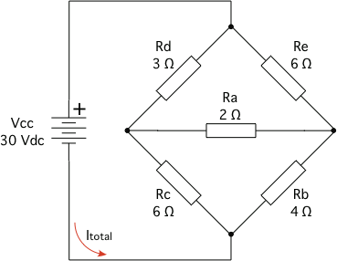
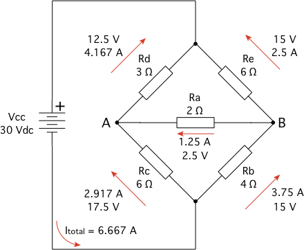
Below is the Bridge Circuit with all the Currents and Voltages shown.
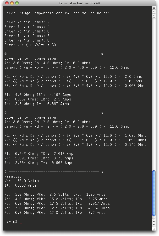
Below are the calculated Values, based on the entered Values from above, using a Python Script I wrote.
The Python Source Code is accessible via the Software & Website Utilities: Sections' Python Code Samples Link, on the Home Page.
©2008 - 2099, Alle Rechte vorbehalten, SJWL