| 12 May 2013 |
| Three Rail Train Detection Explained |
|
|
 |
|
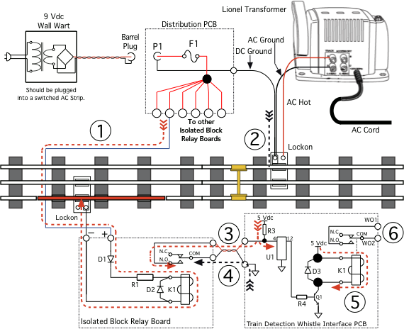
| Unoccupied Isolated Track Section, with related Voltages |
|
|
Note: No Engine or Rail Car is across the Isolated Track Section.
As can be seen above by the heavy dash RED Line,  , 9 Vdc (from the 9 Vdc Wall Wart) is supplied by the Distribution PCB travels to the + Terminal of the Isolated Block Relay Board, through Diode D1 and drops to 8.4 Vdc. , 9 Vdc (from the 9 Vdc Wall Wart) is supplied by the Distribution PCB travels to the + Terminal of the Isolated Block Relay Board, through Diode D1 and drops to 8.4 Vdc.
The 8.4 Vdc then passes through Resistor R1 and Relay K1 and stops at the Isolated Track Section (shown in RED).
The Distribution PCB 9 Vdc Ground Lead, (heavy dash BLACK Line)  , is connected to the Outside Rail. , is connected to the Outside Rail.
Within the Train Detection Whistle Interface PCB 5 Vdc, (heavy dash RED Line)  , is applied to Pin 4 of U1 (the PIXAXE µController), and via the twisted pair Wires to the N.O. (Normally Open) Contact of the Isolated Block Relay Board. , is applied to Pin 4 of U1 (the PIXAXE µController), and via the twisted pair Wires to the N.O. (Normally Open) Contact of the Isolated Block Relay Board.
Also, from within the Train Detection Whistle Interface PCB 0 Vdc (Ground), (heavy dash BLACK Line)  , is applied via the twisted pair Wires to the COM (Common) Contact of the Isolated Block Relay Board. , is applied via the twisted pair Wires to the COM (Common) Contact of the Isolated Block Relay Board.
Also, within the Train Detection Whistle Interface PCB 5 Vdc, (heavy dash RED Line)  , is applied through its Relay K1, and appears on the Collector of Transistor Q1. , is applied through its Relay K1, and appears on the Collector of Transistor Q1.
The Connector Pins WO1 (Whistle Output 01) and WO2 (Whistle Output 02),  , are not shorted since K1 is turned OFF. , are not shorted since K1 is turned OFF. |
|
|
 |
|
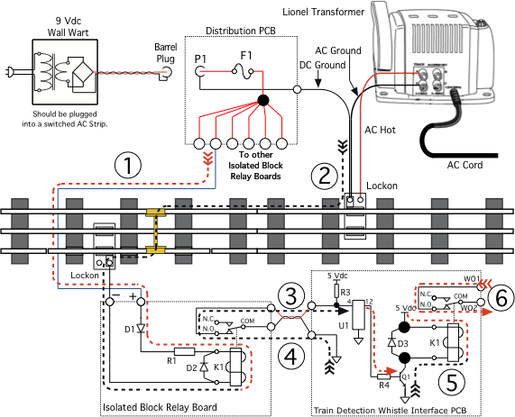
| Occupied Isolated Track Section, with related Voltages |
|
|
Note: Either an Engine or a Rail Car is across the Isolated Track Section.
As can be seen above by the heavy dash BLACK Line, , 0 Vdc (or Ground) which is present on the non-isolated outside Rail, travels through the Wheels Axle (placing the Isolated Track Section at AC (and DC) Ground Potential) to Relay K1 of the Isolated Block Relay Board, causing Relay K1 to turn ON. Remember that 8.4 Vdc, , is still present across K1.
The N.O. (Normally Open) Contact, , of the Isolated Block Relay Board is then connected to the COM (Common) Contact, , pulling Pin 4 of U1, of the Train Detection Whistle Interface PCB, to Ground Potential.
When U1 detects that Pin 4 is at Ground Potential, it place Pin 12 at 5 Vdc, which turns Transistor Q1 ON, which places a Ground Potential, (heavy dash BLACK Line) , to K1, turning the Relay ON.
The Connector Pins WO1 (Whistle Output 01) and WO2 (Whistle Output 02), , are now shorted, which then activates the external Whistle Device.
U1 keeps Relay K1, of the Train Detection Whistle Interface PCB, turned ON for a User selected amount of time, then turns K1 OFF, then ON, and then OFF (each by a separate User selected amount of time). |
|
| The above explanation also applies if one choses to use a 9 Vac Wall Wart, and the Isolated Block Relay Board with the Full Wave Bridge Rectifier for Diode D1, and appropriate Value Resistor R1. |
|
| Return to Three Rail Train Detection Main Page |
|
Created: 12.05.2013, Modified: 20.02.2014
©2008 - 2099, Alle Rechte vorbehalten, SJWL |